PT1000 RTD Simulator (ESP32 + AD5245)
Flash an ESP32 from the browser and set an AD5245 digital potentiometer to the resistance a PT1000 would have at any temperature you choose, so your controller reads a sensor that is not there. Shows the resistance, the temperature it means and the step size the part can actually manage.
1. Flash the board
Put the emulator firmware on a spare ESP32-S3 development board. This overwrites whatever is on it. Nothing is installed on your computer — the flashing protocol runs in this tab.
2. Wire the potentiometer
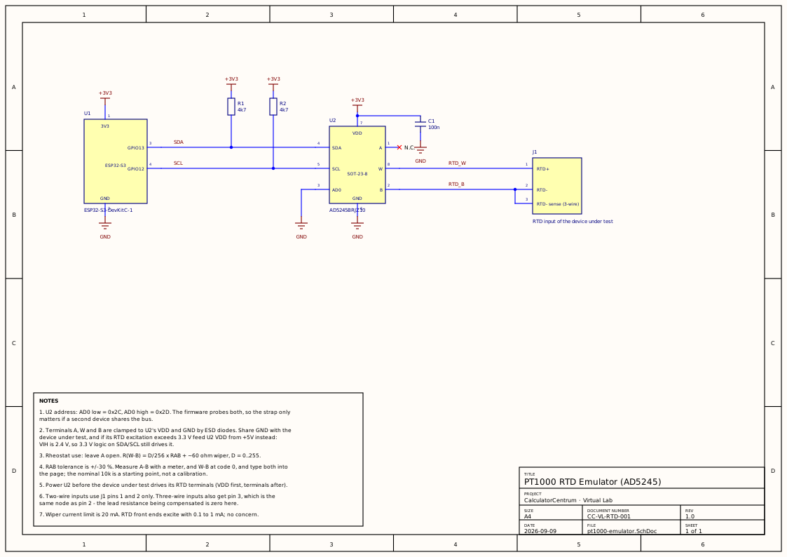
| AD5245 pin | Connect to | Note |
|---|---|---|
| 4 SDA | GPIO13 | 4.7 kΩ pull-up to 3V3 |
| 5 SCL | GPIO12 | 4.7 kΩ pull-up to 3V3 |
| 7 VDD | 3V3 | 100 nF at the pin. 5 V if the controller's excitation needs it |
| 6 GND | GND | Also the controller's ground |
| 3 AD0 | GND | Address 0x2C. Tied high it is 0x2D; the page finds either |
| 8 W | Controller RTD+ | The emulated sensor is the resistance W–B |
| 2 B | Controller RTD− | Three-wire input: the compensation lead goes here too |
| 1 A | Nothing | Leave open for rheostat use |
3. Connect
Use the USB-UART socket if your board has two. Opening a serial port reboots the board, and on the socket wired to the chip's own USB that reboot re-enumerates it, killing the connection as it is being made. A separate bridge chip stays connected across the reset. The potentiometer keeps its last setting through the reboot only if it stays powered; it resets to midscale otherwise, and the page re-sends your value as soon as the link is up.
4. Your potentiometer
The AD5245's end-to-end resistance is specified to ±30 %, so the nominal figure is a starting point, not a calibration. For real numbers, measure A–B with the part unpowered and W–B at code 0, and type them here. The firmware never sees these — they only change which code the page picks and what it tells you the result is.
5. Set the resistance
Not connectedConnect to a board to see whether the potentiometer answers.
Why a fake RTD is useful
Testing anything temperature-driven against a real sensor means changing the sensor's temperature, and that is slow and imprecise: a heat gun overshoots, a freezer takes an hour, and neither lets you sit near an alarm threshold and step across it. A resistor does. Your controller cannot tell a digital potentiometer from a platinum element — both are a resistance across two terminals — so you can sweep its whole operating range in seconds, park just below a trip point, and step over it.
What the page calculates
Two models sit between the slider and the wire. The sensoris the IEC 60751 Callendar–Van Dusen curve for platinum with α = 0.00385, the same one thePT100 / PT1000 calculator uses, so a PT1000 reads 1000 Ω at 0 °C and 1385 Ω at 100 °C. Thepotentiometer is the datasheet's rheostat equation, RWB = D/256 × RAB + RW, with the wiper resistance taken as the part's reading at code 0. Choose a temperature and the page finds the resistance, then the nearest code, then reports the resistance and temperature that code actually produces — which is never quite what you asked for, and the page says by how much.
Where the accuracy goes
Three places, in decreasing order. The end-to-end resistance tolerance (±30 %) dwarfs everything and is why the measured-value fields exist. The step size (RAB/256, about ten degrees of PT1000 on the 10 kΩ part) bounds how close you can land. The part's own linearity and temperature coefficient (45 ppm/°C) are the residue, a few ohms, and are the limit of what typing in measured values can fix. For threshold testing none of this matters; for checking a controller's calibration, measure the pot with a meter for each setting you rely on.
Common questions
- Which browsers can flash a board and talk to it?
- Chrome, Edge, Opera and Brave on Windows, macOS, Linux and ChromeOS — anything Chromium-based on a desktop operating system. Both halves of this page use the Web Serial API, which Firefox and Safari have not implemented and which no mobile browser offers at all. There is no polyfill, so on an unsupported browser the tool says so up front rather than failing halfway through a flash. The reference material below works everywhere.
- Why does the temperature only move in ten-degree steps?
- Because a digital potentiometer is a resistor ladder with 256 taps, and the AD5245 with 10 kΩ end to end places them 39 Ω apart. A PT1000 changes by about 3.85 Ω per degree, so one tap is roughly ten degrees. That is a property of the part, not of this page: the 5 kΩ variant halves the step to five degrees, and nothing in software can do better than the nearest tap. The page shows the step size next to the slider, and when you type a target it tells you the nearest resistance the part can actually reach. For testing alarm thresholds it is usually enough — set the pot one tap either side and watch the comparison flip.
- The page says the resistance is 1388 Ω, but my meter reads 1150 Ω. Which is right?
- Your meter. The AD5245's end-to-end resistance is specified to ±30 %, so a nominal 10 kΩ part can be anywhere from 7 kΩ to 13 kΩ and every tap scales with it. The page can only compute from what it is told, and by default it is told the nominal value. Measure A–B with the pot unpowered, and W–B with the wiper set to code 0, and type both into the fields under “Your potentiometer”. From then on the numbers shown are the numbers the device under test sees, to within the part's own linearity, which is a few ohms.
- Do I need pull-up resistors on SDA and SCL?
- Yes. I²C devices only ever pull the lines down, and resistors pull them back up; with none anywhere the bus never returns to idle. Use 4.7 kΩ to 3.3 V on each line, as in the schematic. The ESP32 enables its internal pull-ups when the bus starts, and at around 45 kΩ they will often make a short bench setup work — but “often” is not what you want from test equipment, and a pot that answers with the wrong code is exactly how a weak pull-up presents.
- What voltage may the device under test put on the sensor terminals?
- Anything between the potentiometer's own GND and its VDD, and nothing outside. The terminals are protected by diodes to the supply rails, so an excitation voltage above VDD forward-biases them and the pot is no longer a resistor. Two consequences: share a ground between the ESP32 and the device under test, and check how the device excites its RTD. Most RTD front ends push 0.1–1 mA through the sensor from a 3.3 V or 5 V reference, which is fine with the pot on 3.3 V. If the excitation goes higher, feed the AD5245 from 5 V instead — its logic threshold is 2.4 V, so the ESP32's 3.3 V I²C still drives it. Also power the pot before the device under test, for the same reason.
- My controller has a three-wire or four-wire RTD input. How do I connect it?
- The extra wires exist to cancel lead resistance, and there is no lead to cancel here — so tie them to the same terminals. On a three-wire input, connect RTD+ to W, RTD− to B, and the compensation lead also to B (pin 3 on the schematic's connector). On a four-wire input, connect both force and sense on one side to W and both on the other side to B. The controller will measure zero lead resistance and report the pot's value directly.
- What does “short the sensor” do?
- It sets the AD5245's shutdown bit, which opens terminal A and connects the wiper directly to B. The device under test then sees roughly the wiper's contact resistance — some tens of ohms — which is far below anything a PT1000 can produce and is what a shorted probe looks like. Controllers are supposed to detect that and raise a sensor fault; this is the quick way to check that yours does. The wiper register is preserved, so clearing the box returns to exactly the previous resistance. An open sensor needs a physical disconnect; the pot cannot produce one.
- Can it emulate a PT100, or a thermistor?
- The firmware can — it just sets a resistance — but the 10 kΩ part cannot usefully. A PT100 spans 18 Ω to 390 Ω, which is codes 0 to 8, so the whole sensor fits in nine taps of 39 Ω. A 1 kΩ variant would suit a PT100, but Analog Devices do not make one in this family. A 10 kΩ NTC is the reverse problem: its curve is steep at the cold end and flat at the hot end, so taps are wasted where you need them. This page therefore stays with the PT1000, where the part's range and the sensor's range happen to overlap well.
- Is it safe to flash a board I am using for something else?
- It overwrites the application, so treat it as destructive. The flash writes a complete image — bootloader, partition table and application — over whatever was there, with no backup step. Nothing is harmed permanently: re-flashing your own firmware restores the board, and the emulator does not touch eFuses or anything else irreversible. But a board you are mid-project with should not be the one you experiment on. Any spare ESP32-S3 development board will do.
- Does anything I do here get uploaded?
- No. There is no server and no account. The page is static, the firmware is a plain 199 kB file served from this site, and the flashing protocol and the serial conversation with your board both run in JavaScript in your tab. The resistances you set and your board's serial number never leave your machine.